International Space Elevator Consortium
June-July 2026 Newsletter
In this Issue:
Editor's Note
President’s Note
Chief Architect’s Corner
ISEC Terminology
ISEC Study Report: “Powering the Space Elevator”
Tether Materials
History Corner
Come Build the Future Today!
Social Media Update
Around the Web
Upcoming Events
Contact Us
Editor’s Note
Dear Space Elevator Enthusiasts,
As you can see, this is the July issue of the ISEC newsletter. June flew by with many personal and professional setbacks on the part of both the primary and assistant editors, so we will skip that month and start fresh with an earlier edition!
I would never endorse skipping anything in the newsletter, but if you only have time for one article, please do not miss the story about Arthur C. Clarke by David Raitt for the History Corner! To quote Rocky from Hail Mary, "Amaze, amaze, amaze!"
Sandee Schaeffer
Newsletter Editor
President’s Note
by Dennis Wright
ISEC at ISDC
As usual, there was a lot of space elevator activity at the International Space Development Conference this year, hence this article. For the first time, the space elevator track at ISDC expanded to two sessions: the morning dedicated to powering the space elevator and the afternoon covering a variety of issues critical for space elevator development.
While the technology for a space elevator climber is close at hand, getting power to it is an open question. The three top contenders are solar power, microwave beaming, and laser beaming. A recently concluded ISEC study report called "Powering the Space Elevator" covers each of these in detail. (See article below by Larry Bartoszek.) The morning session at ISDC featured a talk on each option, followed by an hour-long discussion about their pros and cons. In the end it was left up to the attendee (or reader) to decide which option is best. While the study advanced our understanding of the power question, it is clear that more work needs to be done.
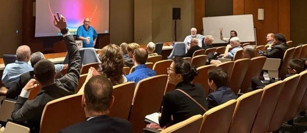
Larry Bartoszek chairing the session on space elevator power.
The afternoon session touched on the Modern-Day space elevator architecture and how it will transform access to space, a quantitative look into the question of whether the space elevator really will be environmentally friendly (looks like it will be), and a comparison of international and US-led approaches to space elevator ownership models. A potential problem for the space elevator tether material was presented: data shows that single crystal graphene actually gets weaker as layers are added. The solution: cross-link the layers by pressure or x-ray bombardment to create periodic diamond bonds.
A delightful interlude was provided by the student team from Ireland who described their large-scale space settlement habitat, complete with a plan of operations. Another avenue of student (and professional) involvement in space was an overview of the World Space Elevator Competitions (www.wspec.org) in which teams from around the world build and test scale-model climbers. Competitions in tether materials and power are also envisioned. How these tethers move and respond to stresses and climber ascent was the topic of the next talk dealing with space elevator dynamics. A talk on the energy efficiency of moving large amounts of mass into space made the point that we need to get used to large numbers before we can really appreciate the economics of space elevators. These large numbers were evident in the final talk on terraforming the Moon. Space elevators are needed!
The session was capped by a lively panel discussion on space elevators and space settlement. The panelists were Bob Zubrin, Pete Swan, Larry Bartoszek, and Steve Griggs, with moderator Dennis Wright. Is the space elevator essential for settlement? Most of the panelists thought so, with some disagreement as to the extent, mode, and location (Earth, Moon, Mars) of space elevator operations. Lots of participation from the audience added depth and new ideas to the discussion. Many of the attendees said that this was the best panel discussion they had ever heard at ISDC.
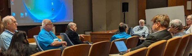
From left to right: Steven Griggs, Larry Bartoszek, Robert Zubrin, Pete Swan.
During the Friday session on planetary defense, ISEC Chief Architect Pete Swan talked about new missions for planetary defense in which space elevators could enhance early asteroid detection. A system of space elevators could see asteroids which come from the direction of the Sun, to which current detection methods are blind. In the Sunday Moon Symposium, he discussed lunar logistics architecture with permanent Earth-based infrastructure involving, you guessed it, space elevators.
Our partner organization, WSPEC (www.wspec.org), hosted two workshops on constructing space elevator climbers. One of these was focused on university students and professionals and the other on middle and high school students. Each participant was given a climber kit and instruction manual. In the time allotted, many completed the assembly of their climber, and these were tested on a tether in the ISEC/WSPEC display area. Some of them actually made it to the top!
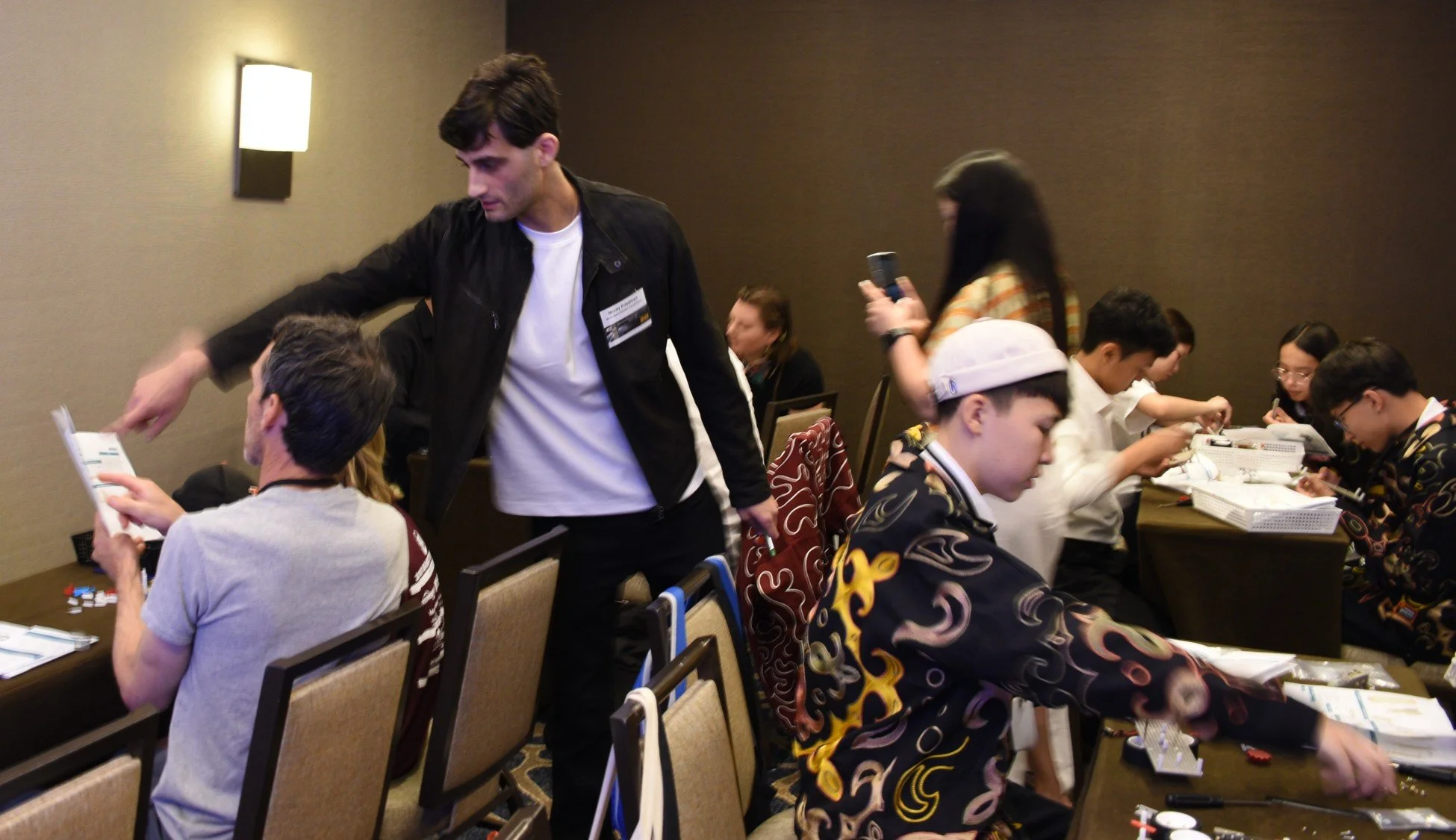
Mordy Friedman assisting participants in one of the space elevator climber construction workshops.
On Friday, an official signing ceremony took place marking the partnership of Space Renaissance International (SRI) (www.spacerenaissance.space), represented by President Bernard Foing, and ISEC, represented by President Dennis Wright. The mission of SRI is to get a large fraction of humanity off-planet in order to ensure its continued existence. The mission of ISEC is to develop the infrastructure to get large amounts of mass into space, so the partnership between us is natural.
ISDC ended on Sunday, but on the way home I had the unexpected treat of talking with Harrison Schmitt, the second to last man to walk on the Moon. Dr. Schmitt gave the Saturday evening banquet talk on his geology work on the Moon. We happened to meet at the gate at Dulles for our flight back to Albuquerque and talked about the Moon, space elevators, weather, and ISDC.
I think ISDC 2026 was one of the best and I hope to see many of you at ISDC 2027 in Los Angeles.
A small selection of the many photographs taken at ISDC2026 "Space-Elevator" events have been uploaded to our Flickr archive, follow this link to view them: https://flic.kr/s/aHBqjCWMSs
Thanks to photographers Laura Bartoszek, Larry Bartoszek, Dorothy Hurley, Aidan Hurley-Kalici, Charlie Krone, Aolani Gonzalez, and the WSPEC team. Photo processing by Peter Robinson.
Chief Architect’s Corner
by Pete Swan
Focusing on “Logistics Giant” at International Space
Development Conference - 2026
This year’s International Space Development Conference was a highlight of the ISEC year with a remarkable range of activities. The early session on Powering the Climber was excellent with a three-hour afternoon session covering a great deal of territory discussing current items of interest while the panel was exciting with discussions on support to Mars and the Moon. It was a very successful four days with a partnership signing and a very active tether climber (and design and build) series of sessions.
In addition, the Chief Architect was fortunate to be invited to present within four topic areas. I chose to emphasize the architectural level of Modern-Day Space Elevators as well as looking at the strengths of permanent transportation infrastructures. My emphasis across the diverse topics was consistent with the description of the “Logistics Giant” for our future. The four presentations were (power point slides coming soon to the ISEC website):
Moon Symposium: “Lunar Logistics Architecture with Permanent Earth Based Infrastructure” – Second chart entitled “Logistics Giant will have no Peer”
Space Elevator Symposium: “Modern-Day Space Elevator Architecture” – focused upon revolutionary and transformational strengths with Logistics Giant explained as our future.
World Space Elevator Competition workshop: A short top-level talk illustrating revolutionary strengths and “Why”.
Planetary Defense Track: “Modern-Day Space Elevators – New Missions for Planetary Defense,” showing operational layouts and the three revolutionary strengths leading to becoming the Logistics Giant.
Each year our interface with the space community at these ISDCs is remarkable and has led to intriguing opportunities to share our belief in the future development of space elevators. Part of the mission for each of us is to ensure the audience can see the future and the phenomenal transformational strengths that differentiate our future successes and then show our remarkable capabilities, as opposed to the impact of the rocket equation and their historic approach to moving off planet. This recognition of a major differentiation of capabilities must be accepted by the audience in order to move forward aggressively. Terminology such as in the following article below should be included in presentations/talks/papers and discussions:
Modern-Day Space Elevators will be Logistic Giants without Co-equals!
ISEC Terminology
by Pete Swan
“Logistics Giant”
The requirement for Why Modern-Day Space Elevator’s will focus upon its new descriptor “Logistics Giant.” The three main revolutionary strengths are:
+ Mover of Massive Logistics to GEO, the Moon and Mars at 170,000 tonnes per year.
+ Delivery Efficiency of 70% of mass at the Earth Spaceport to GEO, Moon, and Mars.
+ It will be the Green Road to Space as it does not burn rocket fuel in the atmosphere nor leave debris.
When looking at the needs of humanity as we move off-planet and continue to improve life on-planet it is obvious that:
Modern-Day Space Elevators will be THE Logistics Giant!
ISEC Study Report: “Powering the Space Elevator”
by Larry Bartoszek
ISEC has just released the latest study report, “Powering the Space Elevator”. We spent over two years researching different ways of delivering power to the climbers on the space elevator. The report starts by showing a reference conceptual design for a 20-tonne climber which was first presented in the 2023 study report, “The Climber-Tether Interface of the Space Elevator”. In Chapter 2, we show all the different sub-systems that need power on a climber, with special emphasis on the primary megawatt (MW) scale drive motors that turn the wheels. This chapter shows how much power is needed if there are as many as eight climbers on the tether at the same time.
With this background, we present chapter by chapter the options for wireless power beaming using either laser light or microwaves (Chapter 3), a solar powered climber (Chapter 5), and a climber fed power through an electrically conductive tether (Chapter 6). We show the pros and cons of each method and what the advantages and technical problems with each are. Chapter 4 covers the different options for power generation on the ground to provide wall-plug power for the power beaming options. Chapter 7 covers the descending climber power problem. While ascending climbers need about a terajoule of energy to reach GEO, climbers that are descending have to dump more than a terajoule of energy off the climber to keep from turning into meteors. Chapter 8 covers some of the more unusual methods that have been proposed to power a climber, such as sending mechanical vibrations through the tether, or using the tether as a waveguide for an external microwave field.
The study report is available for free in pdf form at https://www.isec.org/studies/#powering. Paperback hardcopies can be obtained at lulu.com. The report will also soon be available on Amazon and other book sources.
Tether Materials
by Adrian Nixon
An Apparent Paradox: Graphene Laminate Seems to Become Weaker with More Layers
Dear reader, (spoiler alert - don’t worry): You will know that graphene is one of the world’s strongest materials with a tensile strength of 130 GPa for single crystal graphene. But did you also know that a peer reviewed paper found that as graphene layers are added, this tensile strength decreases? [1]. There is some explaining to do…
This work was based on microscale tests where samples of graphene and multilayered graphene were laid over holes drilled into a graphite substrate rather like the skin on drum. An atomic force microscope was used to press into the graphene covering and the force required to break the graphene was used as a proxy for the tensile strength.
The results were surprising and counterintuitive. They found that the more layers of graphene that were added (up to 8), the lower the tensile strength recorded.
What the researchers realised was that rather than the graphene layers becoming weaker, the layers slid over one another, and this produced the lower strength measurements.
This could be dismissed as an artefact of the test method; however, this test shows us something important about the way graphene laminates behave under tension and pressure. The ability of the graphene layers to slide over one another could compromise larger structures made from this material. So, mitigating this effect is something we need to pay close attention to.
The obvious way of mitigating the sliding of the layers is to form cross links between the graphene layers. We proposed a hypothesis for doing just this and we discovered that a peer reviewed paper confirmed this cross-linking could be created [2].
The cross-linking forms diamond “spot welds” between the graphene layers and the tensile strength and shear strengths are in the order of a hundred gigapascals [3,4].
This means the cross-links between the layers of graphene are of the same order of magnitude of strength as the sheets of graphene they connect. So, as well as preventing the sliding of layers under compressive pressure and tension, they also maintain the structural integrity of any shape made from this material.
So, having discovered a surprising weakness of graphene laminates, we now have a mitigation strategy to preserve the ultra-high strength of this new material by spot welding to create a form of diamond that has an exceptionally high shear strength.
References
1. Falin, A., Cai, Q., Santos, E.J.G., Scullion, D., Qian, D., Zhang, R., Yang, Z., Huang, S., Watanabe, K., Taniguchi, T., Barnett, M.R., Chen, Y., Ruoff, R.S. and Li, L.H. (2017). Mechanical properties of atomically thin boron nitride and the role of interlayer interactions. Nature Communications, 8(1). doi: https://doi.org/10.1038/ncomms15815.
2. Nixon, A. (2025). International Space Elevator Consortium. [online] ISEC.org. Available at: https://www.isec.org/space-elevator-newsletter-2025-september/#tether [Accessed 24 Apr. 2026].
3. Qingkun, L., Yi, S., Zhiyuan, L. and Yu, Z. (2011). Lonsdaleite – A material stronger and stiffer than diamond. Scripta Materialia, 65(3), pp.229–232. doi: https://doi.org/10.1016/j.scriptamat.2011.04.013.
4. Yang, B., Peng, X., Zhao, Y., Yin, D., Fu, T. and Huang, C. (2020). Superior mechanical and thermal properties than diamond: Diamond/lonsdaleite biphasic structure. Journal of Materials Science & Technology, [online] 48, pp.114–122. doi: https://doi.org/10.1016/j.jmst.2020.03.005.
History Corner
by David Raitt
ISEC Chief Historian
Arthur C. Clarke and His Extra-Terrestrial Relays
I’m sure that many people consider Arthur C. Clarke as a science fiction author (which he was, of course) and the person who brought the concept of a space elevator into the mindset of the public.
But 80 years ago, he wrote a short paper entitled, “The Space Station: Its Radio Applications”, typed it up, and circulated six copies of it privately. I have a photocopy of the paper, and it is signed “acc. 25.5.45”. It consists of 19 points, the first of which states:
The Space-station was originally conceived as a refuelling depot for ships leaving the Earth. As such it may fill an important though transient role in the conquest of space, during the period when chemical fuels are employed. Other uses, some of them rather fantastic, have been suggested for the space-station, notably by Hermann Noordung. However, there is at least one purpose for which the station is ideally suited and indeed has no practical alternative. This is the provision of world-wide ultra-high-frequency radio services, including television.
The remaining points in the article expand on this idea, including noting the geostationary orbit, also known as the Clarke Orbit. In 2002, there were over 300 satellites in this orbit, in 2021 there were over 500, while today there are nearly 600. Point 8 of his paper notes,
All these problems [mentioned in previous points] can be solved by the use of a series of space-stations with an orbital period of 24 hours, which would required them to be at a distance of 42,000 km from the centre of the Earth (Fig 1). There are a number of possible arrangements for such a chain, but that shown is the simplest.
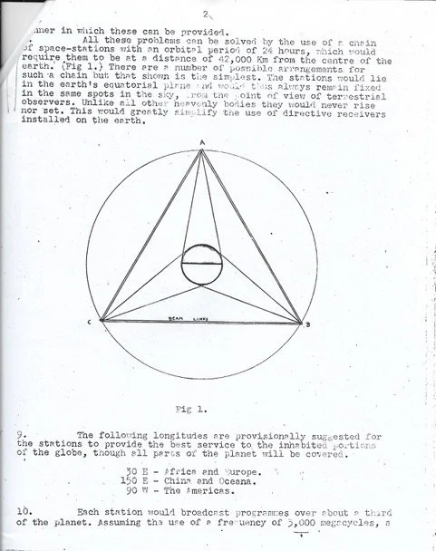
Clearly the recipients of the original paper urged him to publish it and this he did, making it into more of a proper article rather than a list of bullet points. Under the title “The Future of World Communications” it was submitted to Wireless World, accepted almost immediately, and published in the October 1945 issue of the magazine under the revised title “Extra-Terrestrial Relays”. Interestingly, Clarke’s Fig 1 in his original paper (included here as Clarke’s Figure 1) has been replaced by a more refined version in the Wireless World article. The published article can be viewed on this site, which also gives a little more history: https://lakdiva.org.lk/clarke/1945ww/. Mention is made here of a reprint of the Wireless World article in “Ascent to Orbit” – a scientific autobiography of the technical writings of Arthur C. Clarke published in 1984. What this book also includes is Clarke’s paper entitled “The Space Elevator: ‘Thought Experiment’ or Key to the Universe?” first published in 1981 in Advances in Earth Oriented Applied Space Technologies, though presented as an address to the 30th International Astronautical Congress in 1979 in Munich and reprinted in SpaceRef (https://spaceref.com/newspace-and-tech/the-space-elevator-thought-experiment-or-key-to-the-universe-by-sir-arthur-c-clarke/)
In April 2015, the Smithsonian’s National Air and Space Museum acquired a large collection of material, including correspondence, from the Arthur C. Clarke Trust in Colombo, Sri Lanka, representing the life’s work of one of the 20th-century’s foremost science fiction writers and futurists. By 2021, the collection had been scanned and digitized and made available to researchers via the Smithsonian Online Virtual Archives (https://sova.si.edu/record/nasm.2015.0010).
Forty years after Clarke’s article appeared in Wireless World, the magazine presented its readers with a special reprint of it. In the preamble to the paper under the heading “Direct Broadcasting by Satellite – A Brilliant Prediction”, editor Tom Ivall wrote that Clarke had put forward a completely new idea in broadcasting and communications: that transmitters could be carried on artificial satellites of the Earth and thereby achieve excellent coverage with low power very efficiently.
What was so remarkable about Clarke’s article was that it gave the exact conditions for putting a satellite into a geosynchronous orbit and when the first geostationary satellites were launched in the mid-1960s they proved Clarke’s prediction to be absolutely correct.
And what prompted Wireless World to issue a reprint was that the UK had just announced its official state-backed Direct Broadcasting by Satellite (DBS) service on 11 December 1986. The Independent Broadcasting Authority (IBA) awarded the 15-year franchise to a consortium called British Satellite Broadcasting (BSB). Although privately owned companies, BSB and its eventual rival Sky Television (which broadcast using European satellites in 1989) shaped the market. BSB was the first authorized to uplink from British soil, leading to its official launch on March 25, 1990. The two companies merged later that year to form British Sky Broadcasting (BSkyB).
The Smithsonian’s National Air and Space Museum isn’t the only possessor of correspondence with Arthur C. Clarke! When I set up a series of science fiction essay and art competitions at the end of 2002 following my ESA study on “Innovative Technologies from Science Fiction for Space Applications” – which included space elevators – I asked Sir Arthur and Ray Bradbury to lend their names to the competitions. In his endorsement, Sir Arthur wrote,
I want to congratulate you on the initiative to launch a science fiction writing competition. I hope it will attract many entries, and inspire more and more young people to take to writing science fiction. Today's youth take for granted the marvels of modern technology many of which were envisioned in the science fiction of my youth (and some in my own stories!). Please keep me informed of your progress. All good wishes.
Ray Bradbury replied,
Back when I was twelve years old I was madly in love with L. Frank Baum and the Oz books, along with the novels of Jules Verne and H.G. Wells, and especially the Tarzan books and the John Carter, Warlord of Mars books by Edgar Rice Burroughs. I began to think about becoming a writer at that time. [He added,] This is a letter to indicate my complete approval of and admiration for the concept of a Clarke-Bradbury International Science Fiction Competition. I look forward to further developments and will cooperate in every way possible during the next few months. Good luck and best wishes.
Selected stories from the 2003 Clarke-Bradbury International Science Fiction Competition were published by the European Space Agency in September 2004 in SP-546 Tales of Innovation and Imagination. I sent copies to both Sir Arthur and Ray Bradbury, with the former replying with his thanks for the beautiful production. In a follow up letter, a month or so later, he says, “Dear David, I’m still gloating over Tales of Innovation and Imagination! I never imagined when I started writing that one day there would be a Space Agency!” He enclosed a copy of a letter dated 3 December 2004 that he had sent to Ray Bradbury which reads as follows:
Dear Ray, I imagine you have already seen the handsome volume Tales of Innovation and Imagination. When we were using our hard-earned pennies to buy those ridiculous magazines full of absurd stories about flying to the moon and Mars – did we ever dream that one day there would be a ‘European Space Agency’? I can hardly believe it’s just sixty years since I invented the Communications Satellite (I still think it was a good idea). I have never forgotten that the Editor of Wireless World passed the Manuscript over to his assistant and said – ‘Send this crackpot our usual “Kindly Drop Dead” rejection slip’. The assistant talked him out of it, so he said, ‘O.K. we’ll print it, but if it is nonsense you’re fired’. Now of course they’re very proud of having published it.
He wrote by hand at the bottom that he was now completely wheelchaired but would be happy to come to my symposium – if Bill Gates would fly him in his private jet! He also added, “Dear David F.Y.I – all best acc” and asked whether I would be doing Tales every year. On the back of the letter is the comment, “The innovation we need [is] a time controller. Makes real (or subjective time) flow at any rate we desire. Possible?” But this may have been the suggestion of Ray Bradbury who replied to him with this idea written on the side of the letter Sir Arthur sent to him and which had been photocopied by Sir Arthur and enclosed with this letter to me.
Come Build the Future Today!
The International Space Elevator Consortium has launched three special studies to provide more in-depth analyses and conceptual designs for transporting personnel and cargo to space and down-Earth, as well as interplanetary tether launch flight paths and space-traveling vehicles. Space Elevators have claimed to provide superior lift capacity to GEO and beyond compared to rockets. There are a multitude of other benefits that accompany the all-electric launch concepts, which have yet to be quantified.
Two special studies, Clean Ascent Enables Space Settlement and Energy Efficiency Driven Affordability, expand on the preliminary analysis comparing electrically driven space elevators and rocket propulsion. The first study quantifies the pollution byproducts of rocket propulsion and the potential effects it will have on the atmosphere if a mass settlement of space requires thousands of rocket launches per year. The second study compares the energy and power required for sending millions of tons of cargo and personnel to GEO and other planets. Bringing back cargo and personnel from space to Earth, down-Earth, also provides an energy-generation capability that could be useful for a variety of applications, though this has yet to be explored and quantified.
The third special study, Exploring Design in Space Transportation, opens up the imagination and design space for tether-launched spacecraft. Alternative flight paths, not bound by the energy-minimization constraints of rockets, can enable faster travel to destinations in the solar system. Depending on where and when a spacecraft is released from the tether, a variety of velocities and launch angles can be achieved. Space elevators, with a large mass fraction (approximately 70%) for off-world transport, also enable various fuel availability concepts that are unaffordable for rockets.
Do you have an imagination? Do you want to be involved in a design project? The third special study will also open the space vehicle design space to possibilities beyond a flying sewer tube (rocket). A heavy-lift space elevator could deliver a finished space transport vehicle to a launch altitude. However, a large spacecraft to transport a large number of personnel and cargo, built at GEO or above on the tether, then launched, is the really interesting and meaningful concept for this study. A tether approach could be just final assembly, an additive manufacturing-in-space concept, or a mix of both. What would a tether-launched spacecraft look like? How would it be built? How big would it be? How many different design concepts would be needed for various missions? Let your imagination run wild!
ISEC is looking for scientists, engineers, designers, concept builders, manufacturing technologists, human factors, people with imagination, and minds not trapped by what is. We want people who are willing to explore the realm of the possible. No matter how improbable it may seem in today’s world. See the special studies flyers or contact Steve Griggs at steven.griggs@isec.org.
Social Media Update
LinkedIn remains our primary “business” social media outlet, with our follower count now approaching 2400. This now well exceeds the numbers following us on our original social media outlet, Facebook, which has slowly fallen to 2210! We have no easy way of knowing how many people follow us on both, or how many are still active, but we certainly see more engagement on LinkedIn.
If you’re not already following us on LinkedIn, here’s the link: https://www.linkedin.com/company/international-space-elevator-consortium/
For less formal discussion of Space Elevator news and related matters the Reddit community is a useful forum. If you’re a Reddit user, join the conversations on r/spaceelevator.
We occasionally post image and video material on Instagram and YouTube, with several hundred followers on each platform.
For short-message posts we still use X, but engagement has fallen recently as many appear to have left the site. We tried Threads until last year and have persevered with the alternative Bluesky and Mastodon platforms, but engagement is also disappointing: we will be closing the Mastodon account very soon.
On a more positive note, our partner organisation WSPEC has recently created a Discord server, with sections on competition updates and general space elevator news. If you’re a Discord user, join the “WSPEC” community.
In conclusion, if you use any social media platform and see one of our posts, please engage! If you “like” or “re-post” any of our material it will bring it to the attention of your followers and trigger the system algorithm to show it to others. We should all help spread the word that the Space Elevator concept is real, credible, and moving forwards towards becoming a reality; your action might be all it takes to get the attention of some billionaire (or trillionaire!) who could accelerate our progress.
ISEC Media Mogul
Around the Web
Chief Architect Interviewed by Alan Linton
Pete Swan discussed Modern-Day Space Elevators on “Sun Fiver” in two parts:
+ Spaceports (5 minutes): Discussing the unique aspects of having three spaceports on each space elevator. https://www.isec.org/space-elevator-spaceports
+ Architecture (59 minutes): Discussing the current layout of tethers, Galactic Harbours, climbers, power infrastructure and major characteristics/strengths. https://www.isec.org/2026-swan-interview
Gulf News: “Why haven’t we built, or attempted to build, a space elevator yet?”
An insightful newspaper article written by Armen V. Papazian, proposing “funding” of the permanent infrastructure in an appropriate manner while understanding the value of space.
Upcoming Events:
Virtual ISEC Space Elevator Conference 2026
Sponsored by the International Space Elevator Consortium
https://www.isec.org/events/isec2026
Saturday, September 12th, through Sunday September 13th, 2026
WSPEC Central Asia '26
Sponsored by USTEM Foundation
https://www.wspec.org/events
Sunday, August 9th, through Tuesday, August 11th, 2026
Almaty, Kazakhstan
77th International Astronautical Congress
Sponsored by the International Astronautical Federation (IAF)
https://www.iac2026.org/iac-2026
https://www.isec.org/events/77th-international-astronautical-congress
Theme: “The World Needs More Space”
October 5th through October 9th, 2026
Antalya, Turkey
International Space Development Conference 2027
Sponsored by the National Space Society
https://isdc.nss.org/isdc-2027
Thursday, May 27, through Sunday, May 30, 2027
Space Elevator Session, Saturday, May 29
Sheraton Gateway Los Angeles Hotel
78th International Astronautical Congress
Sponsored by the International Astronautical Federation (IAF)
https://www.isec.org/events/iac2027
Monday, September 27th through Friday, October 1st, 2027
Poznań, Poland
Contact Us:
Our website is www.isec.org.
You can find us on Facebook, X, Flickr, LinkedIn, Instagram, YouTube, Bluesky and Reddit.
Support us:
Sign up to be a member at: https://www.isec.org/membership
You can also give directly using the “Donate” link at the bottom of our website page.
Does your place of employment do matching funds for donations or volunteer time through Benevity? If so, you can make ISEC your recipient. Our 501(c)(3) number is 80-0302896.